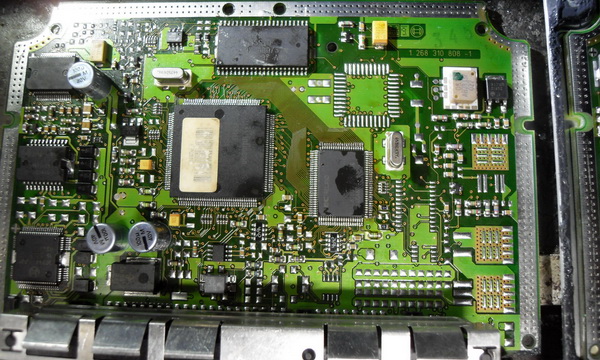
В тырнете нашел вот такой bootloader : скачать......
Для того, чтобы скомпилировать исходник под ваш контроллер, нужно изменить 2 файла:
processor 18F2480
#define OSCF 20000000
#define BAUDRATE 115200
и меняем конфиг , который нам нужен, MCLRE должен быть включен и припаян резистор между первой ножкой контроллера и +5В
settings.inc
{codecitation}
;------------------------------------------------------------------------------
;
; Title: ds30 Loader for PIC18F
;
; File description: user settings and configuration bits
;
; Copyright: Copyright 2009-2012 Mikael Gustafsson
;
;------------------------------------------------------------------------------
;------------------------------------------------------------------------------
; This file is part of ds30 Loader.
;
; ds30 Loader is free software: you can redistribute it and/or modify
; it under the terms of the GNU General Public License as published by
; the Free Software Foundation.
;
; ds30 Loader is distributed in the hope that it will be useful,
; but WITHOUT ANY WARRANTY; without even the implied warranty of
; MERCHANTABILITY or FITNESS FOR A PARTICULAR PURPOSE. See the
; GNU General Public License for more details.
;
; You should have received a copy of the GNU General Public License
; along with ds30 Loader. If not, see .
;------------------------------------------------------------------------------
;------------------------------------------------------------------------------
; Device
;------------------------------------------------------------------------------
processor 18F2480 ;xxx
;------------------------------------------------------------------------------
; Includes
;------------------------------------------------------------------------------
#include "devices.inc"
;------------------------------------------------------------------------------
; User preferences
;------------------------------------------------------------------------------
radix DEC
#define OSCF 20000000 ;xxx oscillator frequency (including pll)
#define BLINIT 2000 ;xxx hello receive timeout [ms]
#define HELLOTRIES 2 ;xxx number of non hello characters received before branching to the user application
#define BLTIME 2000 ;xxx data receive timeout [ms]
;------------------------------------------------------------------------------
; UART settings
;------------------------------------------------------------------------------
#define USE_UART1 1 ;xxx uncomment to use uart1
;#define USE_UART2 1 ;xxx uncomment to use uart2
#define BAUDRATE 115200 ;xxx baudrate
;#define USE_ABAUD 1 ;xxx uncomment to use auto baud rate detection, READ ERRATA FIRST
;#define USE_BRG16 1 ;xxx uncomment to use 16-bit brg
;#define USE_TXENABLE 1 ;xxx uncomment to use a tx enable pin
ifdef USE_TXENABLE
#define TXE_DELAY 10 ;xxx time in us to wait before transmitting after pulling the tx enable pin high
#define TRISR_TXE TRISD ;xxx tris register containing tx enable
#define LATR_TXE LATD ;xxx port register containing tx enable
#define TRISB_TXE TRISD0 ;xxx tris bit for tx enable
#define LATB_TXE RD0 ;xxx port bit for tx enable
endif
;------------------------------------------------------------------------------
; Advanced settings
;------------------------------------------------------------------------------
;#define KICK_WD 1 ;xxx uncomment to kick the wd in the rx loop, only enable if the watchdog is enabled
#define PROT_GOTO 1 ;xxx protect goto at 0x00
#define PROT_BL 1 ;xxx protect bootloader
#define WRITE_VER 1 ;do flash write verification
#define EWRITE_VER 1 ;do eeprom write verification
ifdef IS_PIC18F
#define BLPLP 9 ;bootloader placement, pages from end
#define BLSIZEP 9 ;bootloader size [pages], used by bootloader protection
endif
ifdef IS_PIC18FJ
#define BLPLP 2 ;bootloader placement, pages from end
#define BLSIZEP 1 ;bootloader size [pages], used by bootloader protection
endif
;------------------------------------------------------------------------------
; Configuration bits, these macros can be found at the end of the inc-files located in
; C:\Program Files\Microchip\MPASM Suite\
;
; These can also be set in MPLAB IDE instead, they are found in Configure->Configuration bits...
;------------------------------------------------------------------------------
; xxx
;config RETEN = OFF ;Ultra low-power regulator is Disabled (Controlled by REGSLP bit)
;config INTOSCSEL = LOW ;LF-INTOSC in Low-power mode during Sleep
;config SOSCSEL = LOW ;Low Power SOSC circuit selected
config XINST = OFF ;Disabled
config OSC = HS ;XT oscillator
;config PLLCFG = OFF ;Enabled
config FCMEN = OFF ;Disabled
config IESO = OFF ;Disabled config IESO=OFF
config PWRT = OFF ;Disabled
config BOREN = OFF ;Brown Out Detect
config BORV = 3 ;1.8V
;config BORPWR = MEDIUM ;BORMV set to medium power level
config WDT = OFF ;WDT disabled in hardware; SWDTEN bit disabled
config WDTPS = 32768 ;1:32768
;config CANMX = PORTE ;ECAN TX and RX pins are located on RE5 and RE4, respectively
;config T0CKMX = PORTG ;Timer0 gets its clock input from the RG4/T0CKI pin on 64-pin packages
;config T3CKMX = PORTB ;Timer3 gets its clock input from the RB5/T3CKI pin on 64-pin packages
;config MSSPMSK = MSK7 ;7 Bit address masking mode
config PBADEN = OFF
config LPT1OSC = OFF
config MCLRE = ON ;MCLR Enabled, RG5 Disabled
config STVREN = ON ;Stack Overflow Reset
config LVP = OFF
config BBSIZ = 2048
;config BBSIZ = BB2K ;Boot Block Size
config CP0 = OFF ;Code Protect 00800-03FFF
config CP1 = OFF ;Code Protect 04000-07FFF
;config CP2 = OFF ;Code Protect 08000-0BFFF
;config CP3 = OFF ;Code Protect 0C000-0FFFF
config CPB = OFF ;Code Protect Boot
config CPD = OFF ;Data EE Read Protect
config WRT0 = OFF ;Table Write Protect 00800-03FFF
config WRT1 = OFF ;Table Write Protect 04000-07FFF
;config WRT2 = OFF ;Table Write Protect 08000-0BFFF
;config WRT3 = OFF ;Table Write Protect 0C000-0FFFF
config WRTC = OFF ;Config. Write Protect
config WRTB = OFF ;Table Write Protect Boot
config WRTD = OFF ;Data EE Write Protect
config EBTR0 = OFF ;Table Read Protect 00800-03FFF
config EBTR1 = OFF ;Table Read Protect 04000-07FFF
;config EBTR2 = OFF ;Table Read Protect 08000-0BFFF
;config EBTR3 = OFF ;Table Read Protect 0C000-0FFFF
config EBTRB = OFF ;Table Read Protect Boot
;------------------------------------------------------------------------------
; ds30 Loader commercial version
;------------------------------------------------------------------------------
;-Supports read of flash and EEPROM
;-Supports software UART
;-Supports CAN
;-Available with encryption
;-Read more at www.ds30loader.com
;------------------------------------------------------------------------------
; End of file
;------------------------------------------------------------------------------
{/codecitation}
user_code.inc
{codecitation style="brush: xml;"}
;------------------------------------------------------------------------------
;
; Title: ds30 Loader for PIC18
;
; File description: user init and exit code
;
; Copyright: Copyright © 2011, Mikael Gustafsson
;
;------------------------------------------------------------------------------
;------------------------------------------------------------------------------
; This file is part of ds30 Loader.
;
; ds30 Loader is free software: you can redistribute it and/or modify
; it under the terms of the GNU General Public License as published by
; the Free Software Foundation.
;
; ds30 Loader is distributed in the hope that it will be useful,
; but WITHOUT ANY WARRANTY; without even the implied warranty of
; MERCHANTABILITY or FITNESS FOR A PARTICULAR PURPOSE. See the
; GNU General Public License for more details.
;
; You should have received a copy of the GNU General Public License
; along with ds30 Loader. If not, see .
;------------------------------------------------------------------------------
;------------------------------------------------------------------------------
; UserInit()
; Description: this is executed immediately on start-up before the boot loader code
;------------------------------------------------------------------------------
UserInit macro
; Make uart pins digital
; ifdef ADCON1
; error Do you need to configura uart pins to be digital? If not, remove this line
; endif
movlw b'00001111' ;xxx disable
movwf ADCON1 ;xxx analog on tx/rx
; UART/CAN pps config
ifdef HAS_PPS
ifdef USE_UART2
error You need to configure PPS ;xxx remove this line when PPS is configured
; This template maps U2Rx to RP4
bcf RPINR16, RX2DT2R0 ;xxx
bcf RPINR16, RX2DT2R1 ;xxx
bsf RPINR16, RX2DT2R2 ;xxx
bcf RPINR16, RX2DT2R3 ;xxx
bcf RPINR16, RX2DT2R4 ;xxx
; This template maps RP3 to U2Tx
bsf RPOR3, RP3R0 ;xxx
bcf RPOR3, RP3R1 ;xxx
bsf RPOR3, RP3R2 ;xxx
bcf RPOR3, RP3R3 ;xxx
bcf RPOR3, RP3R4 ;xxx
endif
endif
endm
;------------------------------------------------------------------------------
; UserExit()
; Description: this is executed right before the user application is loadaed
;------------------------------------------------------------------------------
UserExit macro
endm
;------------------------------------------------------------------------------
; End of file
;------------------------------------------------------------------------------
{/codecitation}
Чтобы контроллер "уходил в boot" в своем софте для контроллера нужно делать команду сброса. Например :
Во вкладке "Reset" в приложении "ds30LoaderGui.exe" в поле "Command" нужно ввести ff;ff;ff;ff;ff;ff;ff;ff;ff;ff;ff;ff
{codecitation style="brush: xml;"}
#include< p18cxxx.h>
#include
#include
#include
#pragma config OSC=HS //20 MHz
#pragma config FCMEN=OFF
#pragma config IESO=OFF
#pragma config PWRT=OFF
#pragma config BOREN=OFF
#pragma config BORV=3
#pragma config WDT=OFF
#pragma config WDTPS=32768
#pragma config PBADEN=OFF
#pragma config LPT1OSC=OFF
#pragma config MCLRE=ON
#pragma config STVREN=ON
#pragma config LVP=OFF
#pragma config BBSIZ=1024
#pragma config XINST=OFF
#pragma config CP0=OFF
#pragma config CP1=OFF
#pragma config CPB=OFF
#pragma config CPD=OFF
#pragma config WRT0=OFF
#pragma config WRT1=OFF
#pragma config WRTC=OFF
#pragma config WRTB=OFF
#pragma config WRTD=OFF
#pragma config EBTR0=OFF
#pragma config EBTR1=OFF
//**********************************************************
#pragma udata
char BufferFromPC[13];
#pragma code
void MyHighInt(void);
#pragma interrupt MyHighInt
#pragma code high_vector=0x08
void high_vector(void){
_asm GOTO MyHighInt _endasm
}
#pragma code
void MyLowInt(void);
#pragma interrupt MyLowInt
#pragma code low_vector=0x18
void low_vector(void){
_asm GOTO MyLowInt _endasm
}
#pragma code
void SetInterrupt(void);
void InitUsart(void);
void ClearBuffer(char *buf,int len);
char ParsBuffer(char *buf,int len);
void main(void)
{
ADCON1=0x0f;
TRISCbits.TRISC3=0;
InitUsart();
SetInterrupt();
ClearBuffer(BufferFromPC,13);
while(1)
{
//Здесь контроллер не чего не делает. Бесконечный цикл.
//Контроллер работает только по прерываниям.
//Здесь можно написать какой нить код, например мигать светодиодом.
PORTCbits.RC3=1;
Delay10KTCYx(100);
PORTCbits.RC3=0;
Delay10KTCYx(100);
PORTCbits.RC3=1;
Delay10KTCYx(100);
PORTCbits.RC3=0;
Delay10KTCYx(255);
Delay10KTCYx(255);
PORTCbits.RC3=1;
Delay10KTCYx(255);
Delay10KTCYx(255);
PORTCbits.RC3=0;
Delay10KTCYx(255);
Delay10KTCYx(255);
}
}
//Работаем с COM портом по High прерыванию
void MyHighInt(void)
{
if(PIR1bits.RCIF)
{
getsUSART ( BufferFromPC, 12);
if(ParsBuffer(BufferFromPC,12))
{
_asm
reset
_endasm
}
ClearBuffer(BufferFromPC,13);
}
}
void MyLowInt(void)
{
}
char ParsBuffer(char *buf,int len)
{
int i;
char b;
for(i=0;iСветодиод с таймером :
{codecitation style="brush: xml;"}
#include< p18cxxx.h>
#include
#include
#include
#pragma config OSC=HS //20 MHz
#pragma config FCMEN=OFF
#pragma config IESO=OFF
#pragma config PWRT=OFF
#pragma config BOREN=OFF
#pragma config BORV=3
#pragma config WDT=OFF
#pragma config WDTPS=32768
#pragma config PBADEN=OFF
#pragma config LPT1OSC=OFF
#pragma config MCLRE=ON
#pragma config STVREN=ON
#pragma config LVP=OFF
#pragma config BBSIZ=1024
#pragma config XINST=OFF
#pragma config CP0=OFF
#pragma config CP1=OFF
#pragma config CPB=OFF
#pragma config CPD=OFF
#pragma config WRT0=OFF
#pragma config WRT1=OFF
#pragma config WRTC=OFF
#pragma config WRTB=OFF
#pragma config WRTD=OFF
#pragma config EBTR0=OFF
#pragma config EBTR1=OFF
//**********************************************************
#pragma udata
char BufferFromPC[13];
char cntLED;
#pragma code
void MyHighInt(void);
#pragma interrupt MyHighInt
#pragma code high_vector=0x08
void high_vector(void){
_asm GOTO MyHighInt _endasm
}
#pragma code
void MyLowInt(void);
#pragma interrupt MyLowInt
#pragma code low_vector=0x18
void low_vector(void){
_asm GOTO MyLowInt _endasm
}
#pragma code
void SetInterrupt(void);
void InitUsart(void);
void ClearBuffer(char *buf,int len);
char ParsBuffer(char *buf,int len);
void main(void)
{
ADCON1=0x0f;
TRISCbits.TRISC3=0;
TMR1H=0x00;
TMR1L=0x00;
T1CON=0b00110001;
cntLED=0;
InitUsart();
SetInterrupt();
ClearBuffer(BufferFromPC,13);
while(1)
{
//Здесь контроллер не чего не делает. Бесконечный цикл.
//Контроллер работает только по прерываниям.
//Здесь можно написать какой нить код, например мигать светодиодом.
}
}
//Работаем с COM портом по High прерыванию
void MyHighInt(void)
{
if(PIR1bits.RCIF)
{
getsUSART ( BufferFromPC, 12);
if(ParsBuffer(BufferFromPC,12)){ Reset(); }
ClearBuffer(BufferFromPC,13);
}
else if(PIR1bits.TMR1IF)
{
PIR1bits.TMR1IF=0;
if(cntLED==4)
{
PORTCbits.RC3^=1;
cntLED=0;
}
cntLED++;
TMR1H=0x00;
TMR1L=0x00;
}
}
void MyLowInt(void)
{
}
char ParsBuffer(char *buf,int len)
{
int i;
char b;
for(i=0;iСкачать проект.
{codecitation style="brush: xml;"}
#include< p18cxxx.h>
#include
#include
#include
#pragma config OSC=HS //20 MHz
#pragma config FCMEN=OFF
#pragma config IESO=OFF
#pragma config PWRT=OFF
#pragma config BOREN=OFF
#pragma config BORV=3
#pragma config WDT=OFF
#pragma config WDTPS=32768
#pragma config PBADEN=OFF
#pragma config LPT1OSC=OFF
#pragma config MCLRE=ON
#pragma config STVREN=ON
#pragma config LVP=OFF
#pragma config BBSIZ=1024
#pragma config XINST=OFF
#pragma config CP0=OFF
#pragma config CP1=OFF
#pragma config CPB=OFF
#pragma config CPD=OFF
#pragma config WRT0=OFF
#pragma config WRT1=OFF
#pragma config WRTC=OFF
#pragma config WRTB=OFF
#pragma config WRTD=OFF
#pragma config EBTR0=OFF
#pragma config EBTR1=OFF
//**********************************************************
#pragma udata
char BufferFromPC[13];
char test[11]={'P','I','C','1','8','F','2','4','8','0','!'};
char flagMSG;
char cntLED;
#pragma code
void MyHighInt(void);
#pragma interrupt MyHighInt
#pragma code high_vector=0x08
void high_vector(void){
_asm GOTO MyHighInt _endasm
}
#pragma code
void MyLowInt(void);
#pragma interrupt MyLowInt
#pragma code low_vector=0x18
void low_vector(void){
_asm GOTO MyLowInt _endasm
}
#pragma code
void SetInterrupt(void);
void InitUsart(void);
void ClearBuffer(char *buf,int len);
char ParsingReset(char *buf,int len);
char ParsingHello(char *buf);
void SendMsgToUsart(char *buf,int len,int delay);
void main(void)
{
ADCON1=0x0f;
TRISCbits.TRISC3=0;
TMR1H=0x00;
TMR1L=0x00;
T1CON=0b00110001;
cntLED=0;
InitUsart();
SetInterrupt();
ClearBuffer(BufferFromPC,13);
flagMSG=0;
while(1)
{
//Здесь контроллер не чего не делает. Бесконечный цикл.
//Контроллер работает только по прерываниям.
//Здесь можно написать какой нить код, например мигать светодиодом.
if(flagMSG)
SendMsgToUsart(test,10,50);
}
}
//Работаем с COM портом по High прерыванию
void MyHighInt(void)
{
if(PIR1bits.RCIF)
{
getsUSART ( BufferFromPC, 12);
if(ParsingReset(BufferFromPC,12)){ Reset(); }
if(ParsingHello(BufferFromPC)){flagMSG^=1;}
ClearBuffer(BufferFromPC,13);
}
else if(PIR1bits.TMR1IF)
{
PIR1bits.TMR1IF=0;
if(cntLED==4)
{
PORTCbits.RC3^=1;
cntLED=0;
}
cntLED++;
TMR1H=0x00;
TMR1L=0x00;
}
}
//Принимаем сообщения CAN по LOW прерыванию
void MyLowInt(void)
{
if(PIR1bits.TMR1IF)
{
PIR1bits.TMR1IF=0;
PORTCbits.RC3^=1;
TMR1H=0x00;
TMR1L=0x00;
}
}
char ParsingReset(char *buf,int len)
{
int i;
char b;
for(i=0;i


